
It was not easy for enthusiasts to engage in helicopter development on the eve of World War I. "Aeroplanists" easily spoke of multi-hour flights, 200-kilometer speeds, and dozens of kilograms of cargo. Vast opportunities lay ahead for aircraft builders!
But what about Yuriev and his fellow aeronautics club members? Besides theoretical developments, they had experiments with flying models and... a multitude of technical, production, and financial problems. There was no money to build a demonstration model, no one to manufacture the main shaft of the lifting rotor from scarce chrome-nickel steel, and no suitable steel tubes for the blade spars could be found anywhere. Even bearings had to be ordered from abroad. The treasury did not consider supporting the inventors. "As students, we didn’t want to resort to private initiatives, and no such offers were made," recalled Academician B. Yuriev. "The few entrepreneurs interested in aviation preferred to copy 'proven' foreign designs."
Countless delays in private workshop orders forced Yuriev and his colleagues to suspend the construction of their single-rotor helicopter (as it turned out, until 1921) and focus on a multi-engine design—a concept explored by N. Zhukovsky in his work "On the Useful Load Lifted by a Helicopter." At the same time, the "Yurievites" experimented with a specially built lifting rotor. They did not have a suitable engine, so Yuriev adapted a lightweight two-stroke motor for this purpose. However, the war began, and many of Zhukovsky’s students, including Boris Nikolaevich, donned military uniforms.
Helicopter designers abroad did not achieve much success either, and the war completely halted their work. Only Austria-Hungary showed special interest in rotary-wing aircraft. In 1916, Petrocci, an officer at one of Austria’s flight schools, proposed a helicopter project intended to replace tethered observation balloons, from which officers monitored enemy movements and corrected artillery fire via telephone. The enemy, of course, tried—and often successfully—to shoot down the dangerous but unfortunately stationary observer.
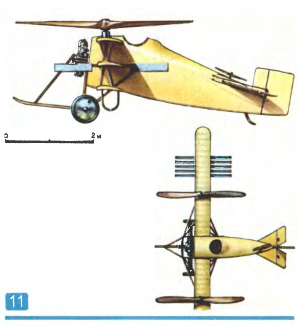 |
| 11. Berliner’s helicopter (USA, 1921). Engine — rotary, 110 hp. Lifting rotors — two-bladed, fixed-pitch, wooden, diameter — 4.5 m; rotation speed — 560 rpm. Flight weight — 600 kg. To transition from vertical takeoff to horizontal flight, a 1-meter diameter propeller was installed in the tail section of the aircraft. |
And so, the Viennese strategists concluded that a compact tethered helicopter would be a less vulnerable target. Petrocci's aircraft, equipped with a 300-horsepower Daimler electric motor, received power via a cable and could remain in the air indefinitely.
A similar project was developed and implemented by Professor T. von Kármán (later a world-famous aerodynamicist and one of the founders of supersonic flow theory) and engineer Zurovec. The conditions of wartime prevented the refinement of tethered helicopters. However, the vast experimental data—Petrocci alone conducted numerous tests with large rotors about 6 meters in diameter—proved invaluable to post-war aerodynamic scientists and practical designers.
In France, Professor Lacoin and engineer Damblanc built a helicopter that would be called today a transverse-scheme design. The machine never flew, but its distinguishing feature—a transmission linking both rotors and the potential ability to fly even if one engine failed—later became a standard feature of all multi-rotor helicopters.
Across the ocean, in the suburbs of Washington, engineer G. Berliner built two helicopters between 1919 and 1923, one of which achieved notable results for its time. Initially, the designer constructed a fuselage-less aircraft with two coaxial, counter-rotating rotors. A small surface behind the pilot was used for control. After ascending to a height of 5–6 meters, Berliner realized the aircraft was unstable and switched to an entirely different design. He positioned two small four-meter rotors on either side of an airplane fuselage and added a tail propeller with a vertical axis of rotation—this was intended to "tilt" the aircraft's tail so that the rotors would generate a horizontal thrust component for forward movement. Lateral control was provided by surfaces (similar to ailerons) at the ends of the frame supporting the lifting rotors. Later, these frames evolved into a triplane structure, giving the aircraft both airplane-like gliding capabilities and helicopter-style control: the axes of the lifting rotors could be tilted together or separately in any direction.
 |
|
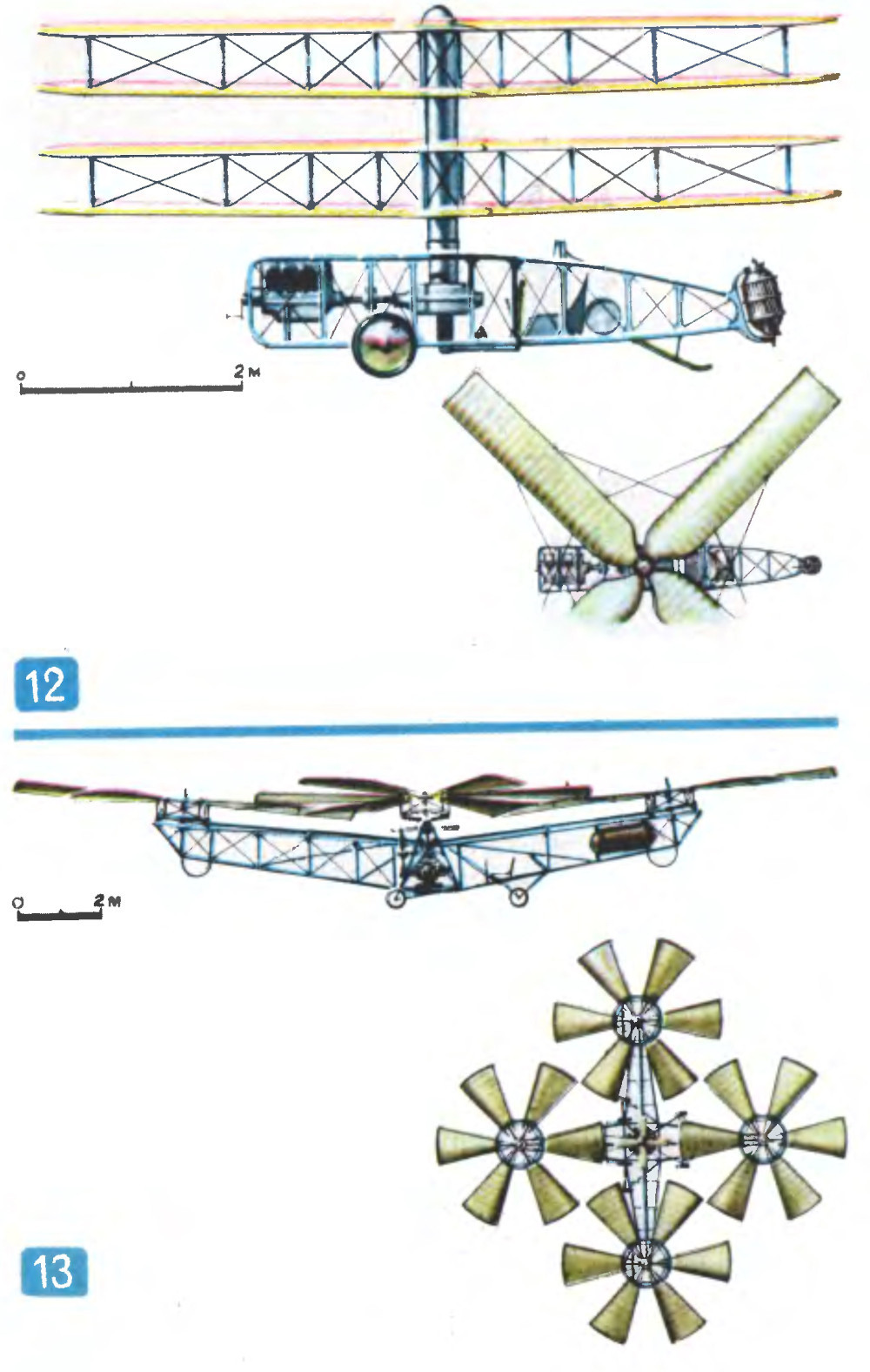
12. Pescara Helicopter (Spain, 1922). Engine - "Hispano-Suiza," 180 hp. Diameter of coaxial biplane counter-rotating rotors - 7.2 m. 13. G. Botezat Helicopter (USA, 1922). Rotary engine "Le Rhône," 180 hp. Four six-bladed variable-pitch lifting |
In December 1922, in Dayton—the city of the famous Wright brothers—flights began for the helicopter designed by G. Botezat, a former professor at the Petrograd Technological Institute. Botezat opted for a multi-rotor design: differential, independent control of rotor thrust promised reliable maneuverability in the vertical plane, or simply put, the ability to adjust the helicopter’s nose position relative to the horizon. Four six-bladed rotors were positioned at the ends of a cross-shaped frame made of steel tubes with piano wire braces. Two small horizontal-thrust rotors were used for directional control and turns during hover. Until the spring of 1923, G. Botezat, along with pilots T. Bain and A. Smith, conducted several successful flights. In one of them, the helicopter lifted a useful load of 450 kg to a height of 4 meters.
Spanish designer P. Pescara created a series of successful helicopters. His first coaxial helicopter was built in 1919–1920 in Barcelona, but the machine hovered for only about a minute at a height of 1.5 meters. Flights of other models, one of which is shown in Figure 12, lasted much longer.
In 1923, French engineer E. Oemichen developed an extremely complex aircraft, equipping his four-rotor machine with six additional small propellers to maintain balance and provide control along all axes. Two more rotors were used for horizontal flight.
For greater stability, Oemichen installed a massive gyroscopic flywheel on the engine shaft, which also stored mechanical energy in case of an engine failure. As a result, the helicopter remained stable for half a minute even when the control stick was released. This was confirmed by commission members who witnessed its eight-minute flight along a triangular 1,100-meter route on May 4, 1924.
In the cover image: E. Oemichen's helicopter (France, 1922). Rotary engine "Le Rhône," 120 hp. Diameter of lifting rotors along the longitudinal axis — 6.4 m, along the transverse axis — 7.5 m. Total lifting rotor area — 41.1 m². Rotor drive — tubular shafts through a gearbox.